
February 2019

In last week’s exciting instalment, I’d got as far as working out where all the hole positions were relative to each other with the help of a plastic template. The next job was to measure this up, make myself a nice drawing…
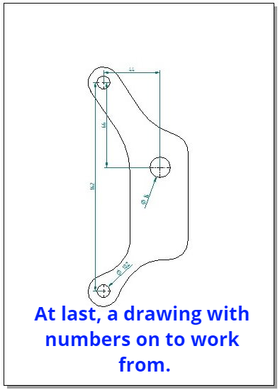
…and then produce an identical template for the other side.
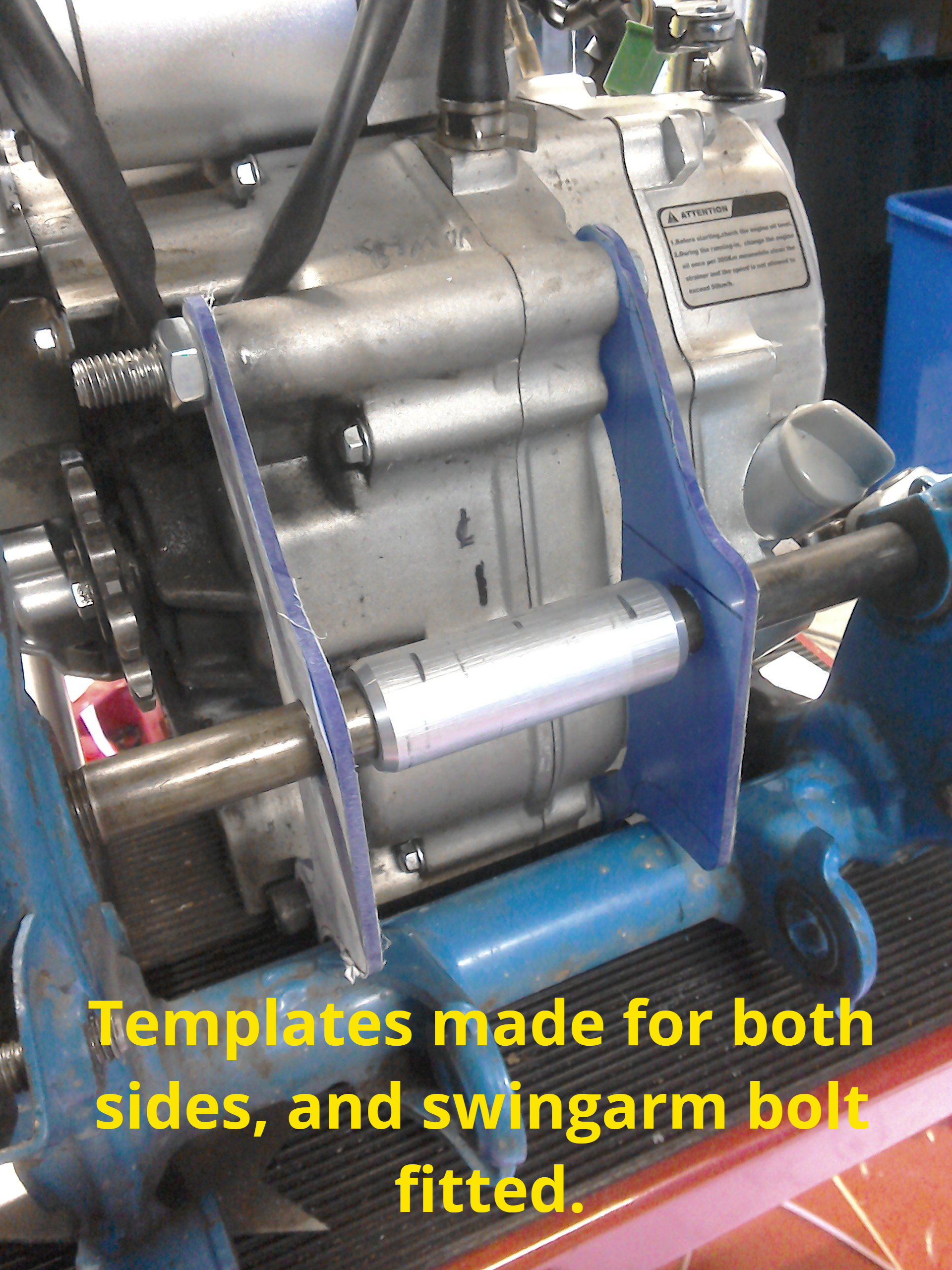
Originally, the swingarm bolt would have passed through the rear of the engine’s crankcases, but this engine isn’t so designed. So, instead, the plan is to try and replicate this with mounting plates that bolt to the new engine. These can’t be flat (like the templates currently are) they have to be offset inwards so that they fit in the gap that the aluminium spacer currently occupies.
Back to the drawing board then for some more sketches and thinking, for as well as needing the mounts to be offset, for space reasons (more accurately, lack of space reasons!) they also have to bolt on after the engine is in the frame. But that’s not the only problem, because once the engine is in the frame, you can’t actually insert a bolt into the engine’s bottom mount hole (the frame rail is in the way).
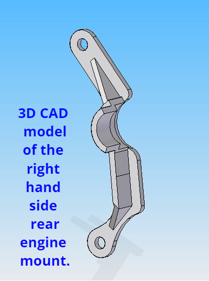
A bit of a conundrum to overcome! Initially I’ve decided to make the mount in two halves, a left side and a right side. After looking around the garage to see what I could use to prototype the mounts, I suddenly remembered that I own a 3D printer, so back on the computer to produce a 3D model to work from.
A bit of a conundrum to overcome! Initially I’ve decided to make the mount in two halves, a left side and a right side. After looking around the garage to see what I could use to prototype the mounts, I suddenly remembered that I own a 3D printer, so back on the computer to produce a 3D model to work from.
So I’m currently waiting for the printer to print them for me, it takes around 5 hours for each mount. Next week, I’ll let you know if they fit…
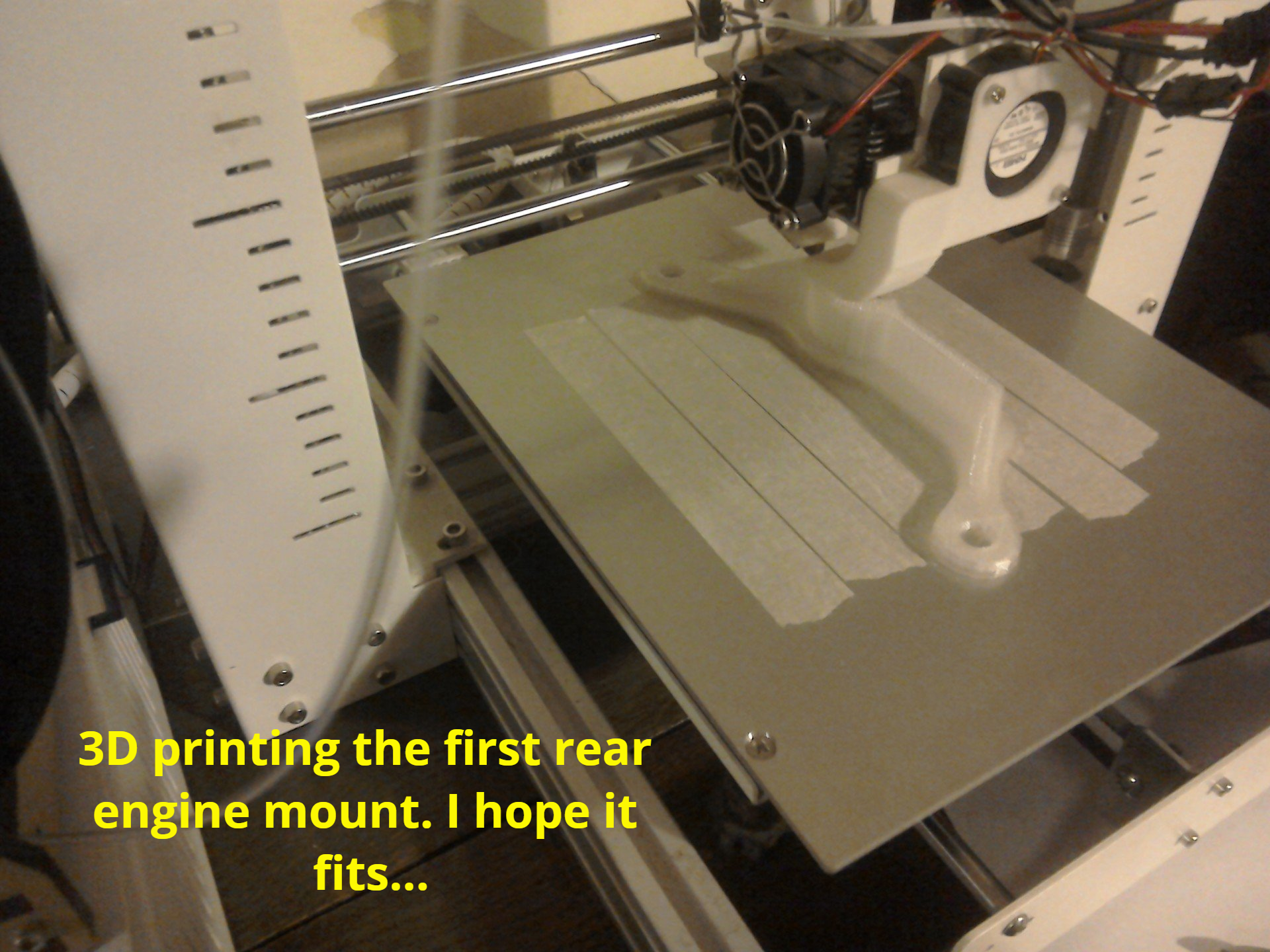
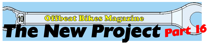
First side of the engine mount is off the 3D printer and it does, at least, look the correct shape. Just time for a quick photo, before scurrying off to the garage to see if it fits…
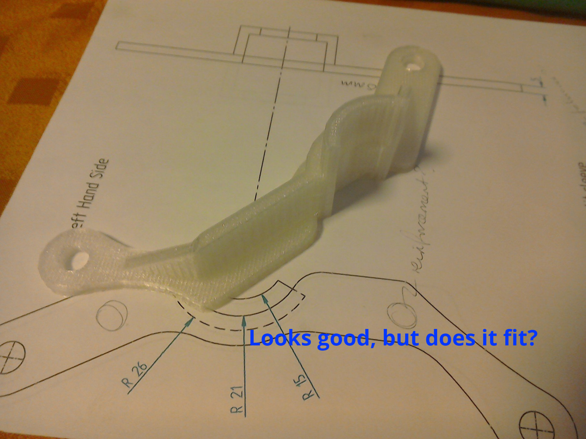
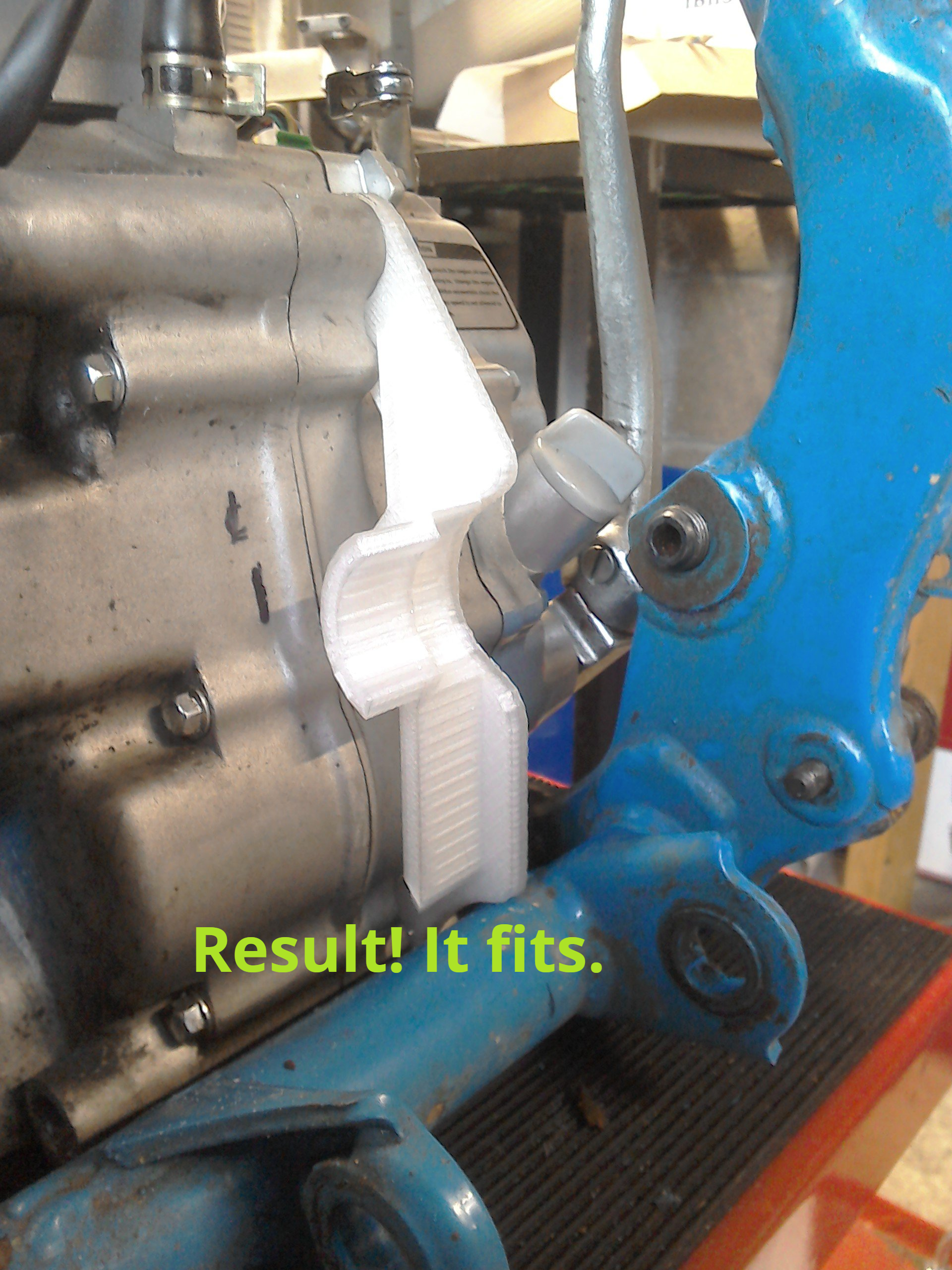
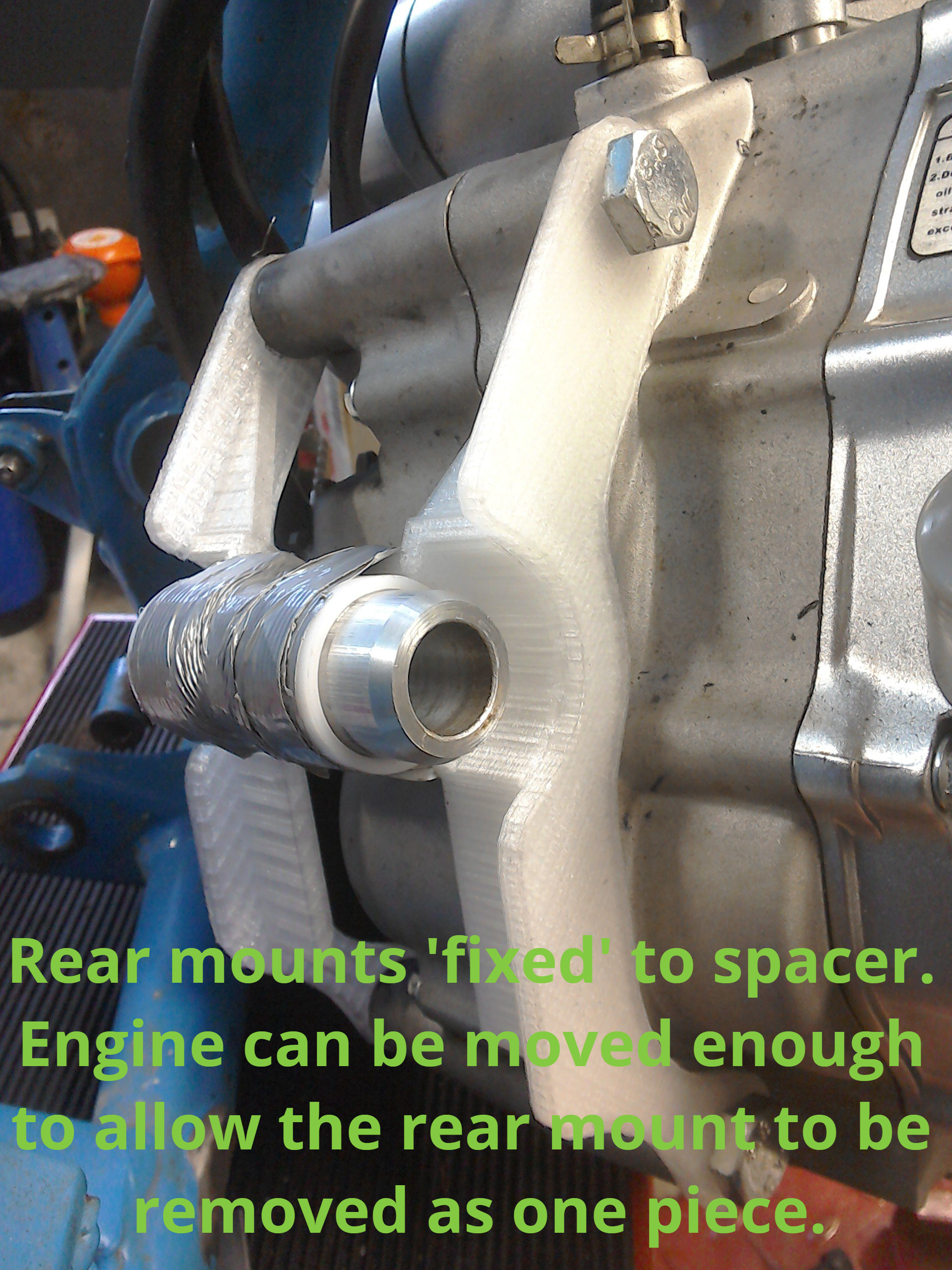
Originally, I’d designed the mounts in two halves so that they could bolt on after the engine was in the frame (as previously mentioned) but I wanted to see if the engine could possibly be removed with the mounts in place. So, with the aid of some sticky tape, the 3D prototypes were fixed to the aluminium spacer and an attempt made to take the engine out of the frame.
The result…
Well, no you can’t get the engine out of the frame with the rear mounts on, but you can move it far enough to allow them to be removed as a single unit. And so, the new plan is that the rear mount will be fabricated as a single unit.
The result…
Well, no you can’t get the engine out of the frame with the rear mounts on, but you can move it far enough to allow them to be removed as a single unit. And so, the new plan is that the rear mount will be fabricated as a single unit.
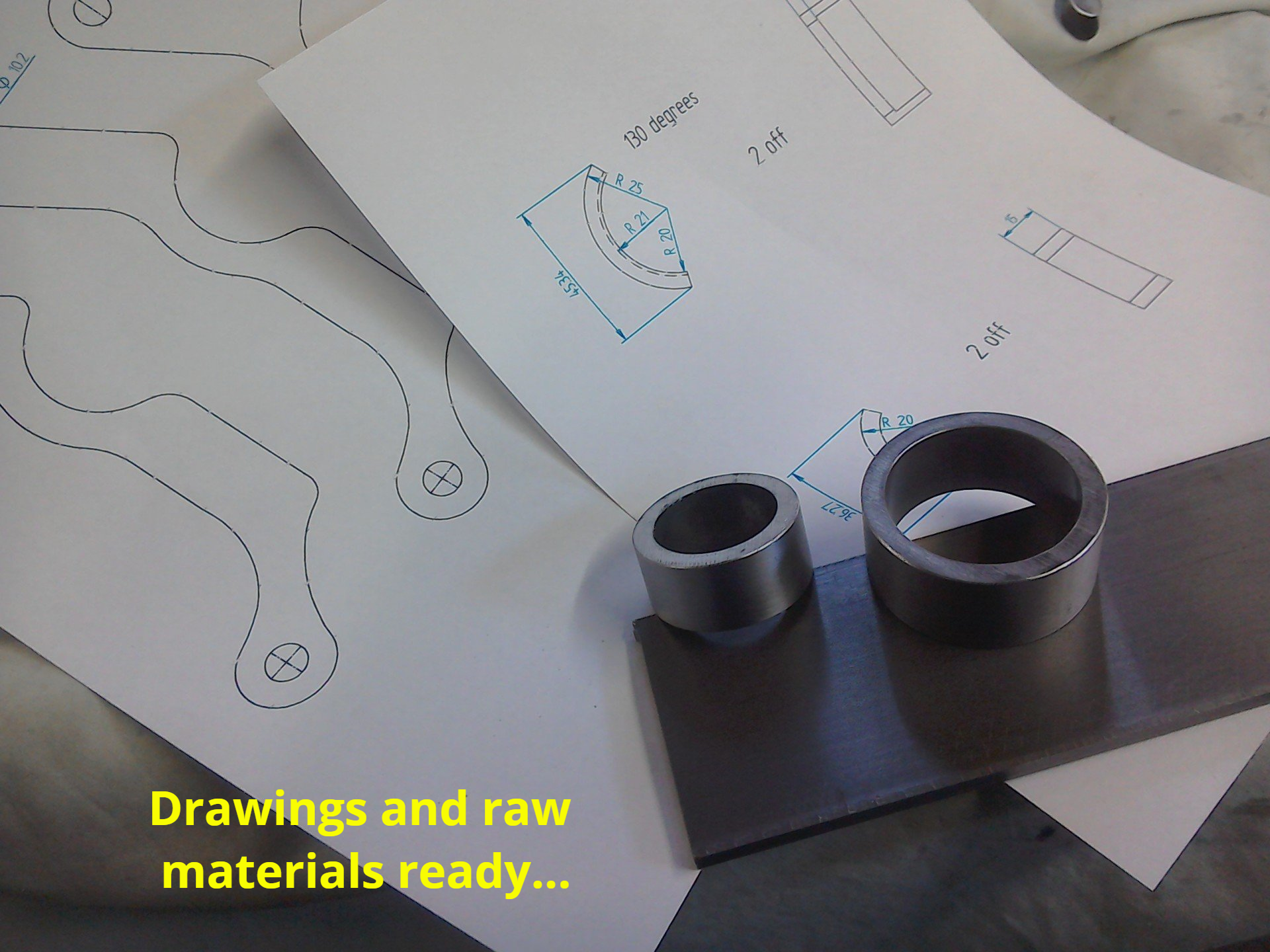
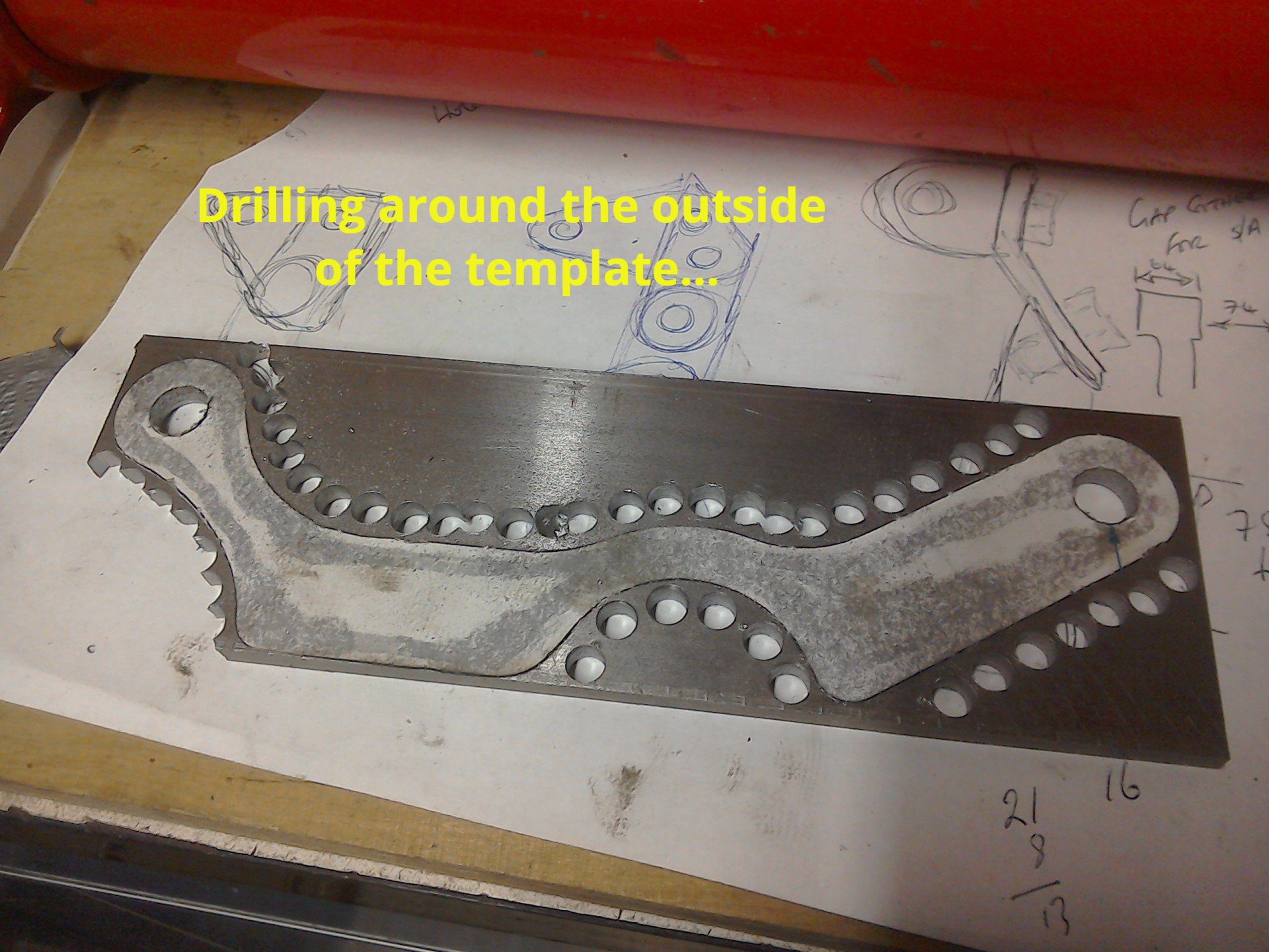
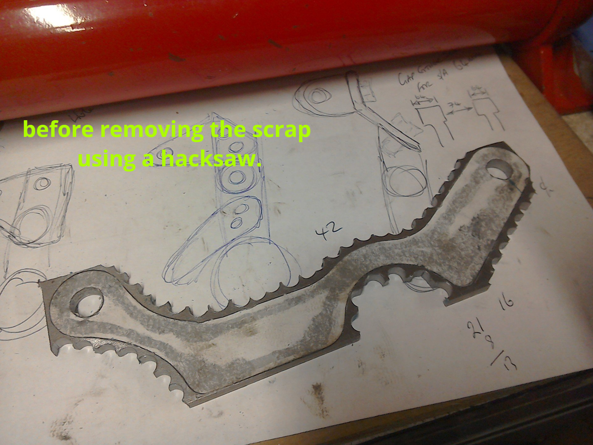
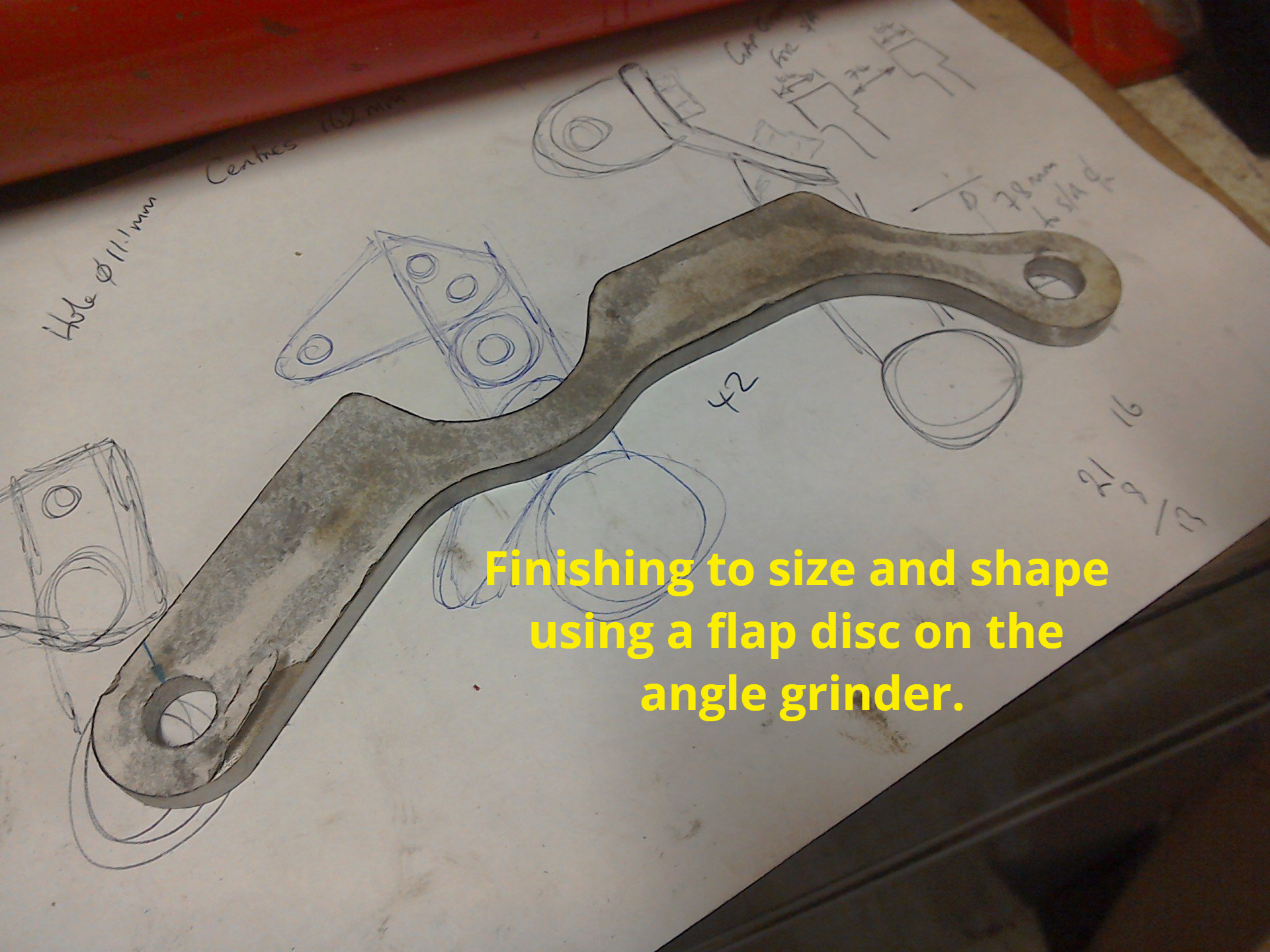
Time, then, to start building them for real. These are going to be fabricated from steel, so its a case of more drawing, drilling, grinding and filing.
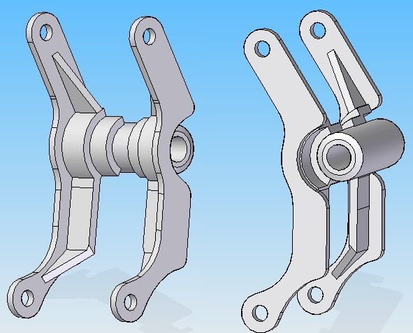
A picture is supposed to be worth a thousand words, so rather than try to describe the final design of the rear engine mount, here it is in 3D CAD. Front view on the left. Rear view on the right.
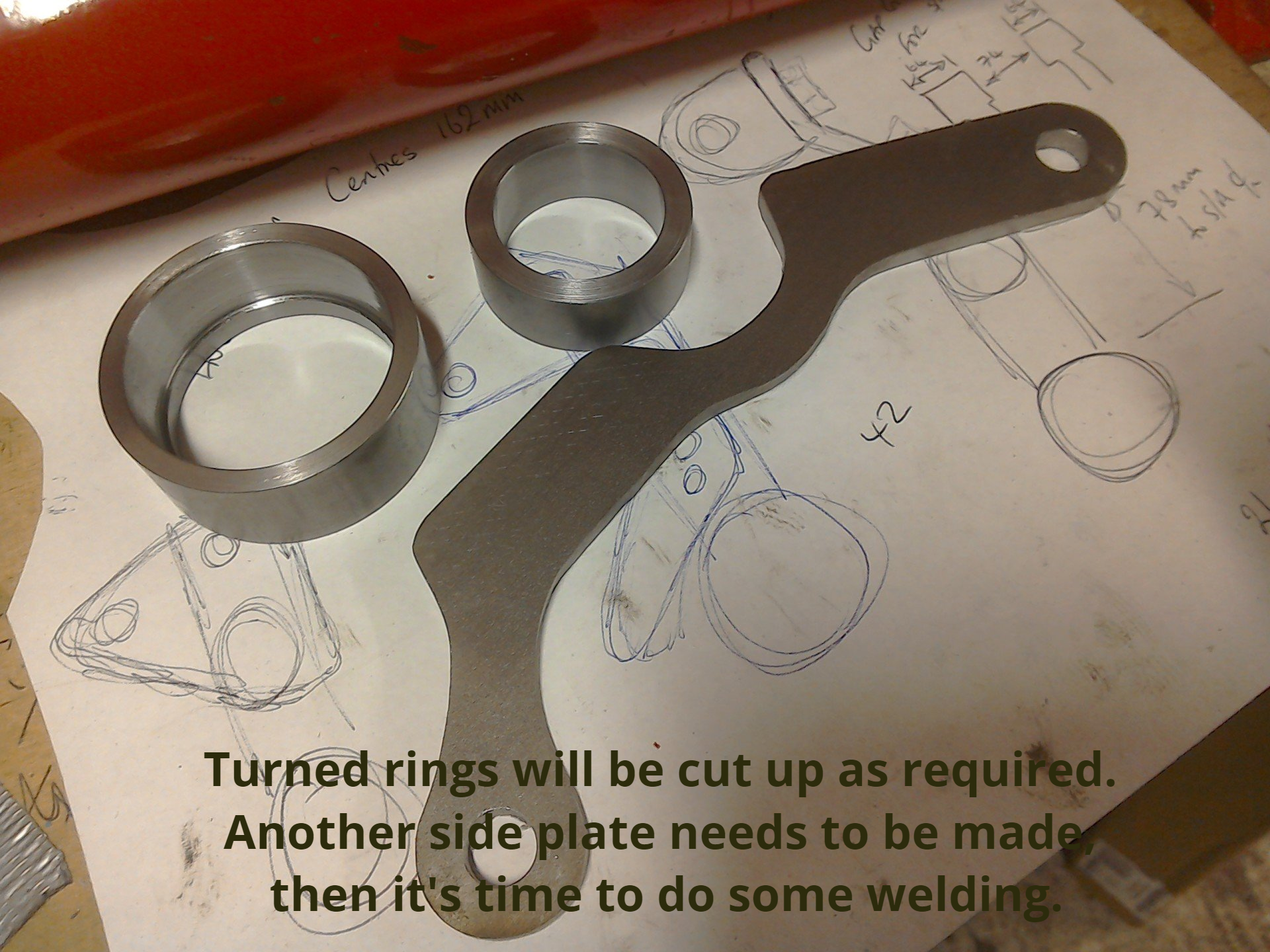
The intention is to fabricate the mount in two halves; left side and right side, before finally joining them to the spacer that the swingarm bolt will pass through.
The intention is to fabricate the mount in two halves; left side and right side, before finally joining them to the spacer that the swingarm bolt will pass through.
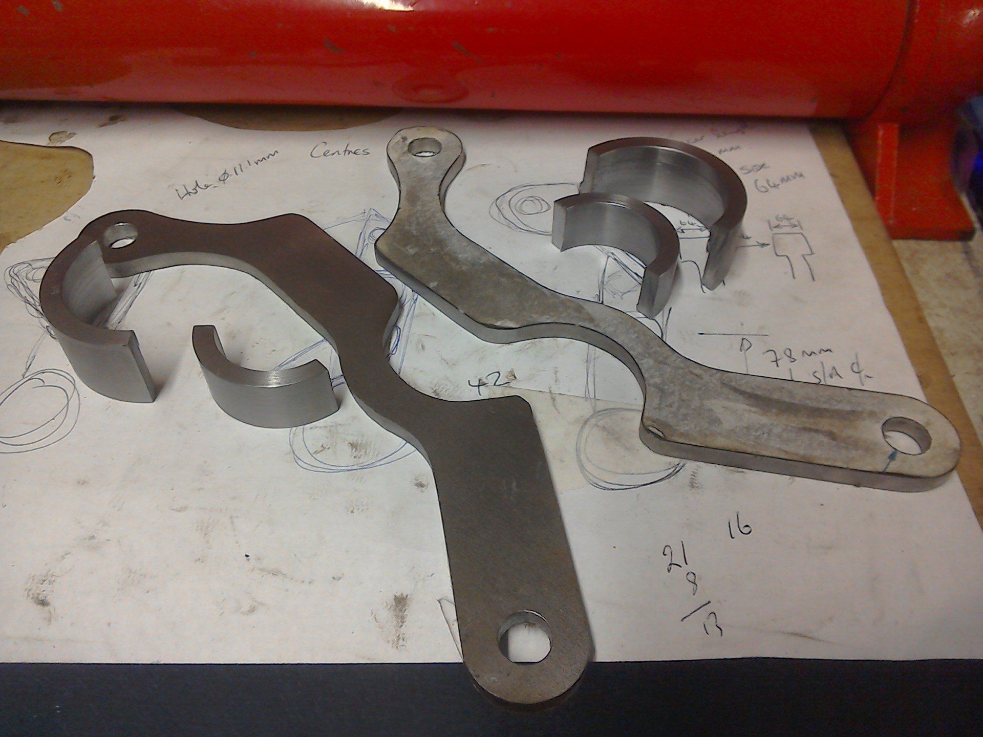
Most of the individual bits have been fabricated (apart from the spacer) and the two turned rings cut. The two curved parts to the left of picture have been cut to the correct length. Those on the right still require finishing. (And I also need to remove the paper templates!)
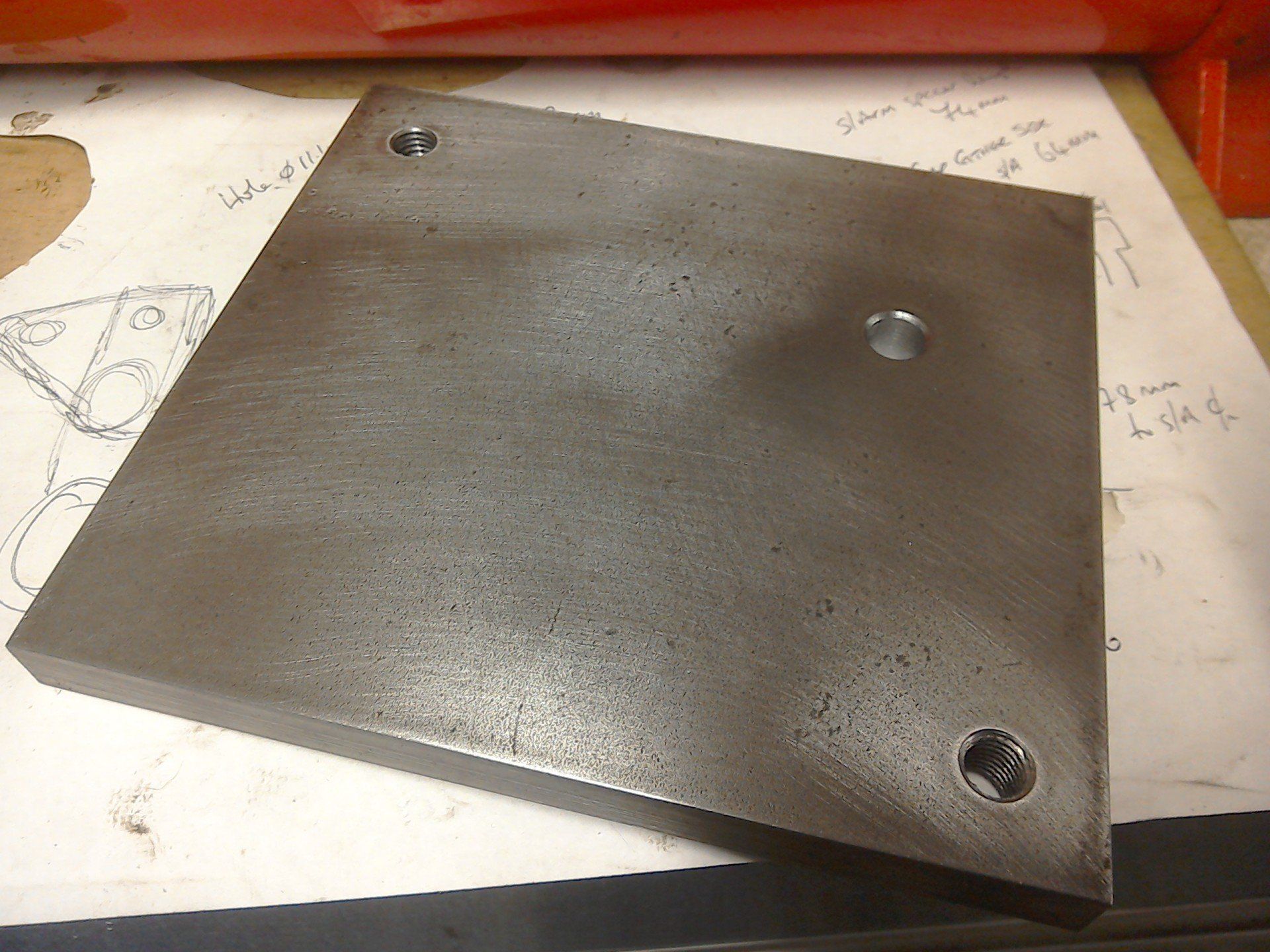
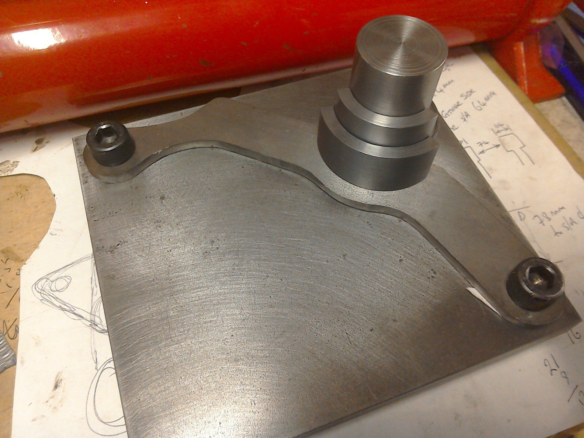
This is the jig that will (hopefully) hold everything together whilst it's being welded. It's a flat 12mm steel plate, with holes drilled and tapped to hold the flat part of the engine mount in place. The third hole allows a turned support to be added, which will hold the curved parts in place (with the aid of suitable clamps).
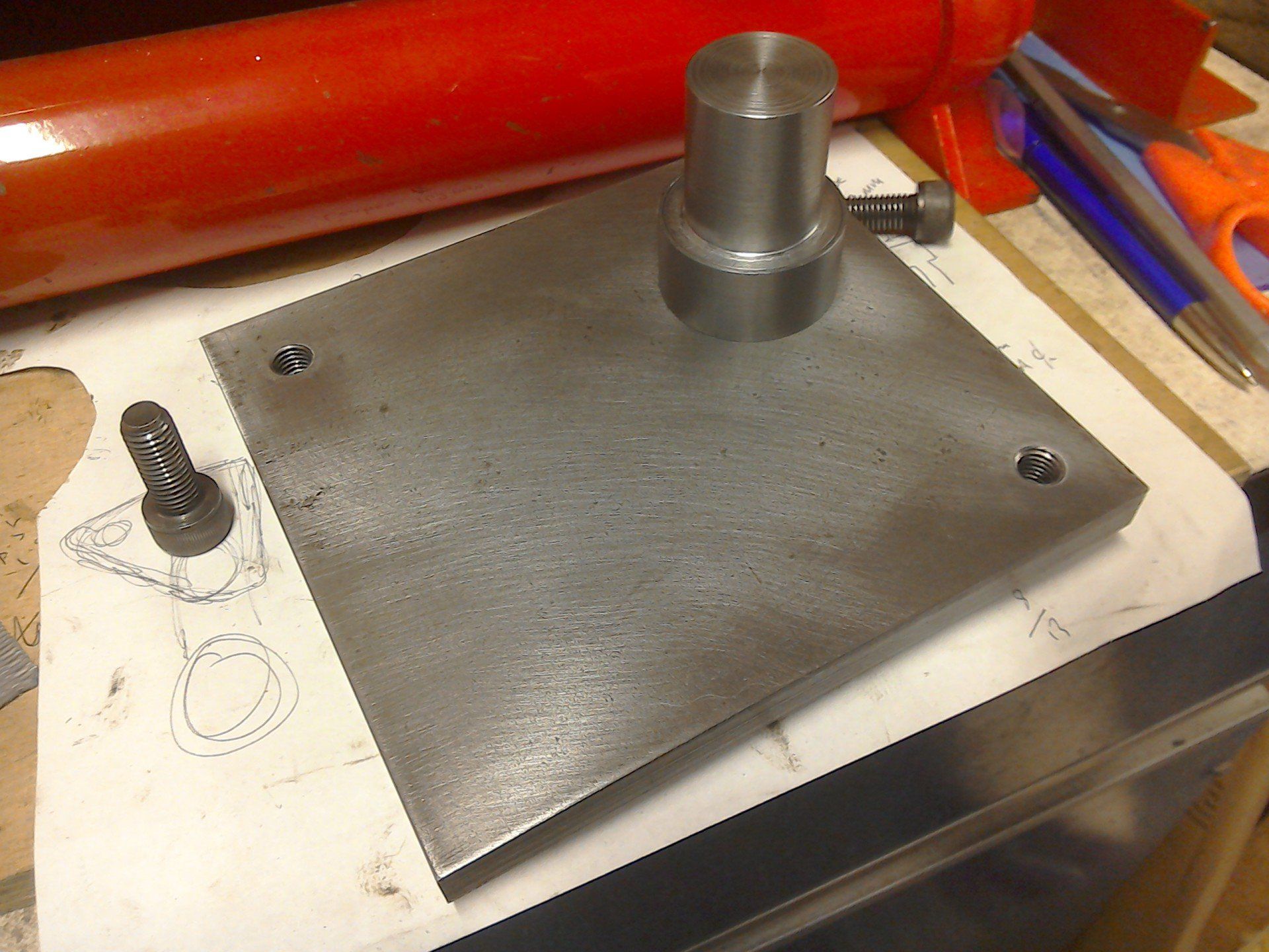
BELOW: Turned support bolted in place.
Flat part of engine mount bolted in place.
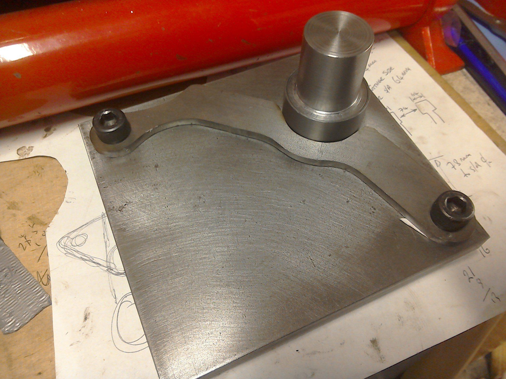
The two curved parts are added, held in place by the turned support.
As the two parts of the mount are handed, once this half is done, the jig is turned over and everything bolted to the other side for the second half to be constructed.