Yamaha SRX600 Replacement Speedo
The elderly Yamaha needs a new speedo. For years it has run a succession of bicycle speedos as the non-standard front wheel meant that the mechanical speedo drive would no longer fit and I wanted a cheap replacement. And those bicycle speedos have done the job admirably, except they don’t last. After the last one packed up, I went in search of a replacement, and seduced by the thought of no wiring and magnets required, picked a GPS one. Now technically I’m not sure that a GPS speedo is legal, but I think we’ll be okay. So, after a search on the internet, looking at the various options, I picked a GPS speedo that best matched my budget and requirements, so once again it was a bicycle one…Now I just needed to mount it.
The old bicycle speedo had been mounted in the shell of the original mechanical speedo in a variety of ways over the years. The last iteration had the display mounted in the ‘glass’.
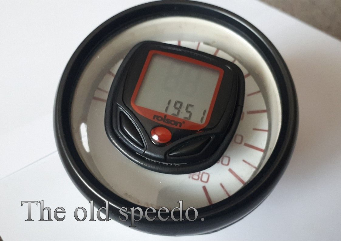
The bezel, glass and speedo unit was removable to allow easy battery replacement. In use it was held in place by a giant rubber band made from a slice of an old inner tube.
The new speedo had some challenges, the buttons were side mounted and the unit is USB rechargable, so once again easy removal would be desirable, and I really wanted to cover up the CYCPLUS logo.
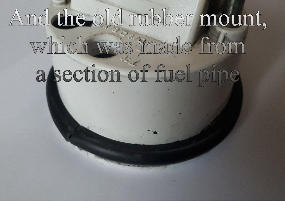
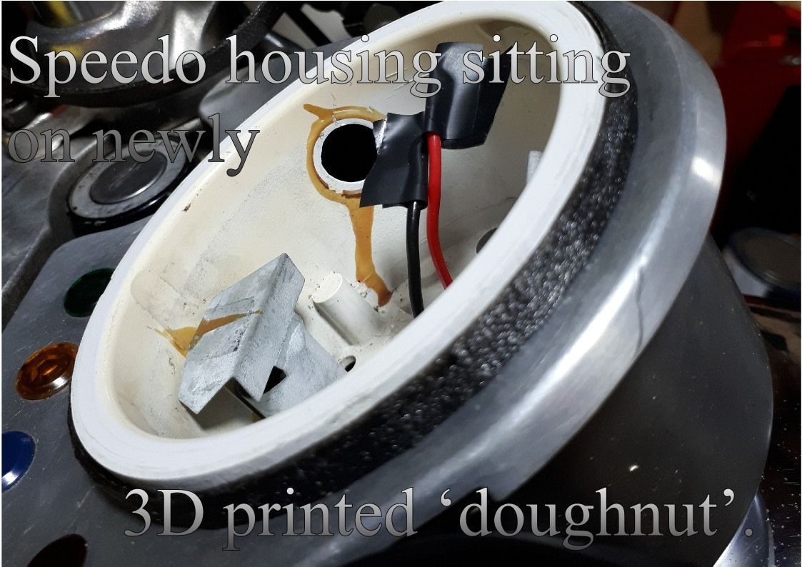
Speedos (well certainly the old mechanical ones) were usually also rubber mounted to deal with any vibrations. The rubber mounts had long since deteriorated on mine and been replaced by some rubber fuel pipe glued in place. With the TPU filament still mounted in the 3D printer, I also wanted to see if I could improve on this.
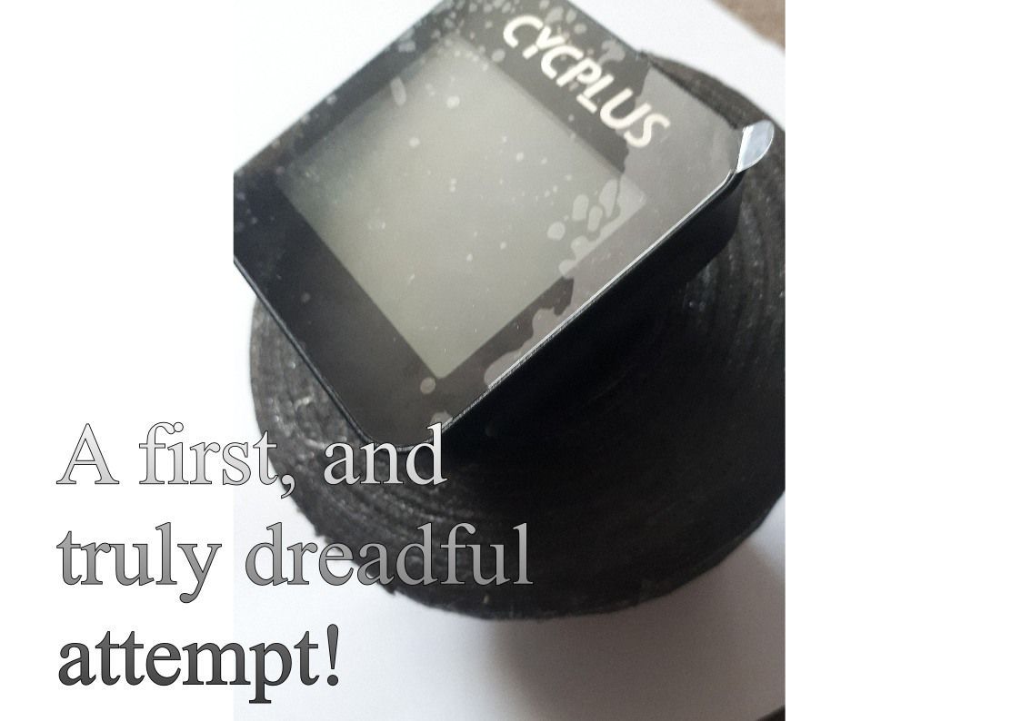
First designs were not at all promising and soon a graveyard of discarded 3D prints was starting to pile up.
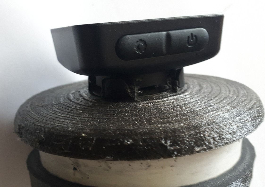
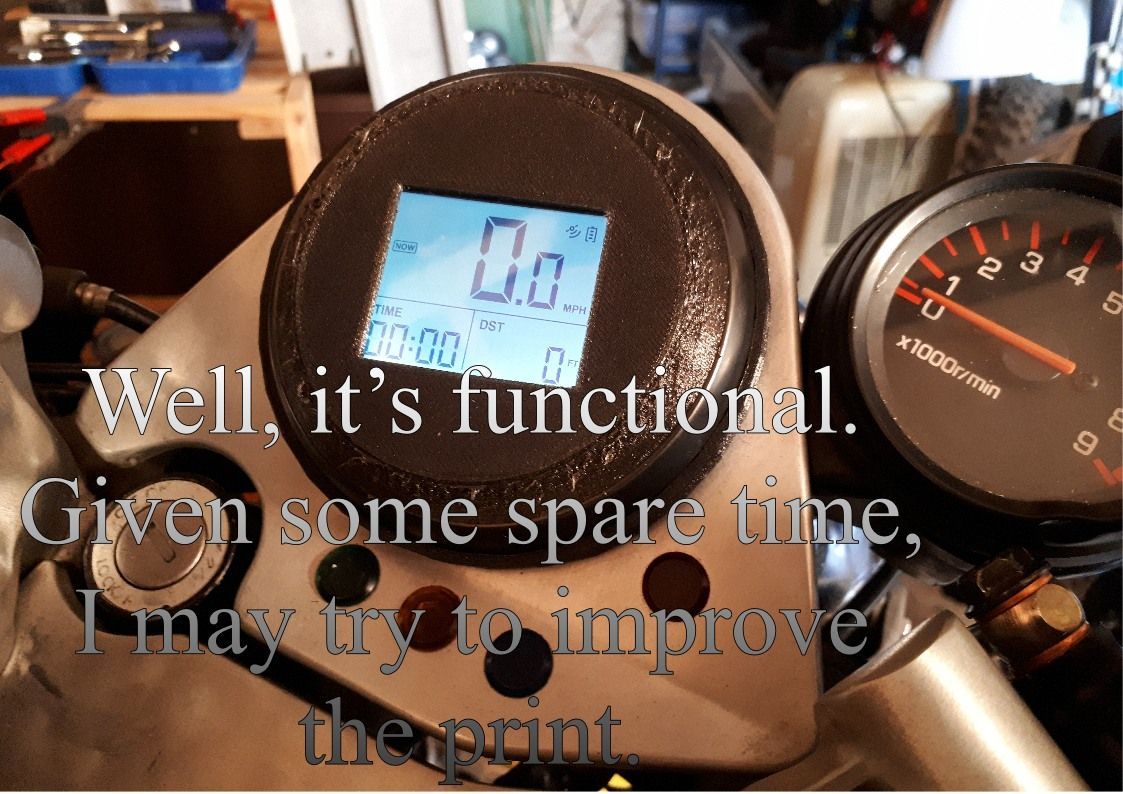
Eventually I produced something which is okay. Not great, but okay.
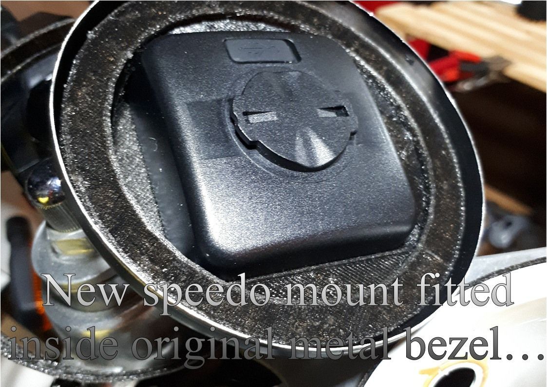
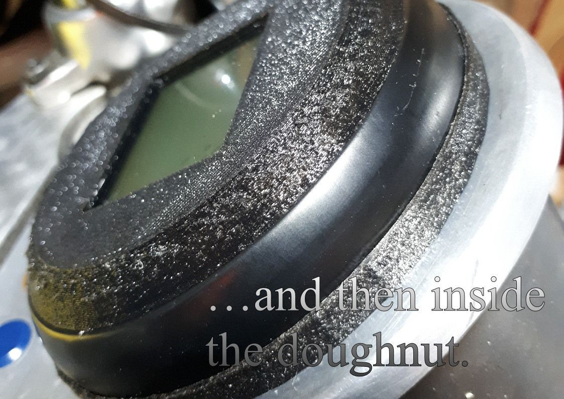
It’s a 3 part mount. First part is a rubber doughnut that replaces the old fuel pipe. This also has a lip that the original mounting bezel fits in.
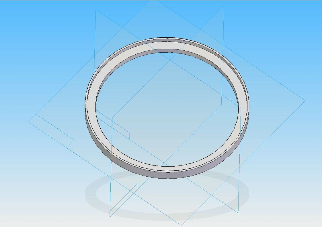
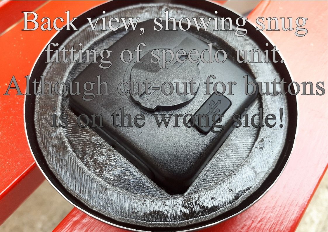
Fitting in the original bezel is the unit that holds the new speedo. It has a window on the front which is the exact size of the LCD display (so covering up the logo) and a recess in the back in which the speedo unit sits snugly on three sides.
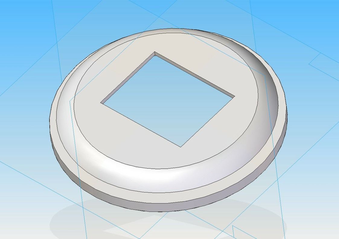
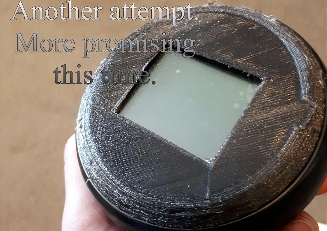
The fourth side has a gap to allow access to the buttons. Or it would if I hadn’t made a mistake at the design stage and put the gap on the wrong side. (LCD display is not symmetrically located on the speedo unit, so I couldn’t just turn it 180 degrees to cover up my error.) Anyway, it works as it is for the moment.
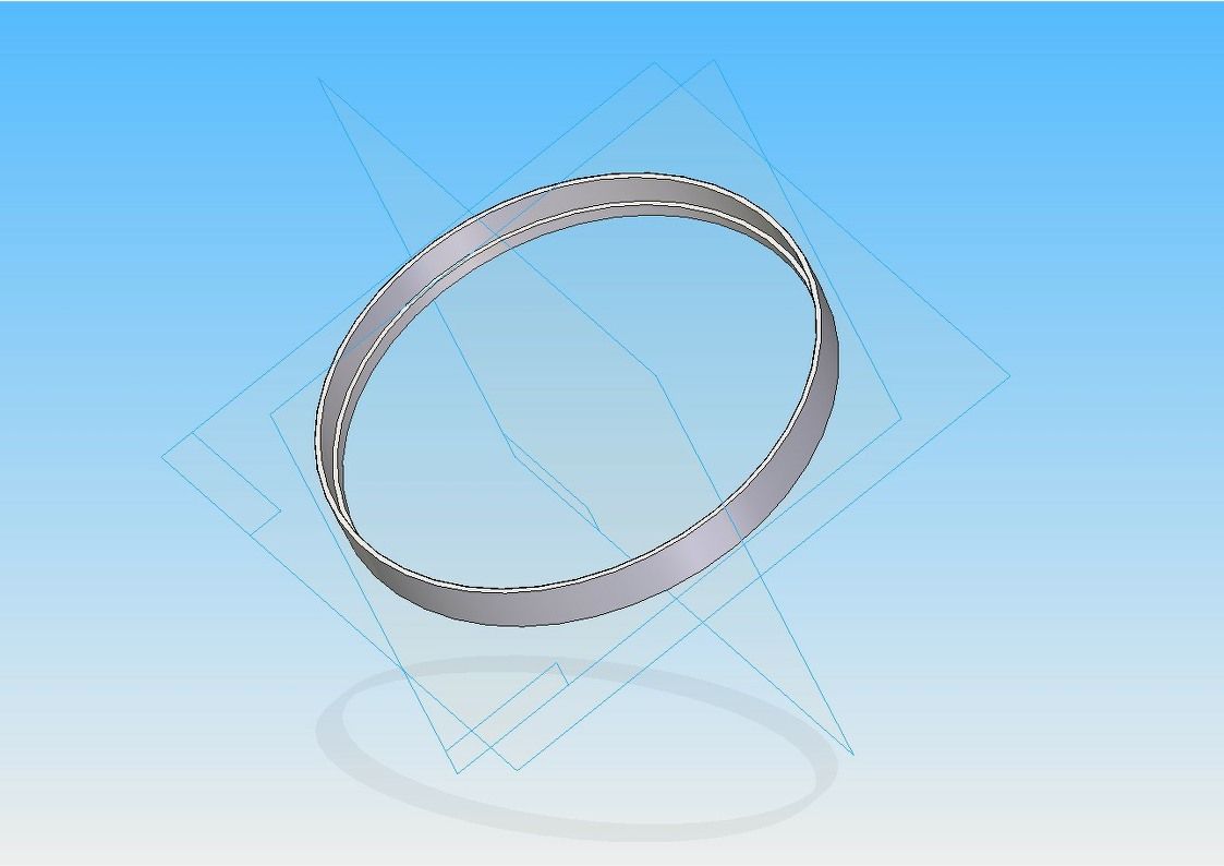
The third part is then a 3D printed ‘elastic’ band to replace the old inner tube band to hold everything in place and stop bits from falling off.
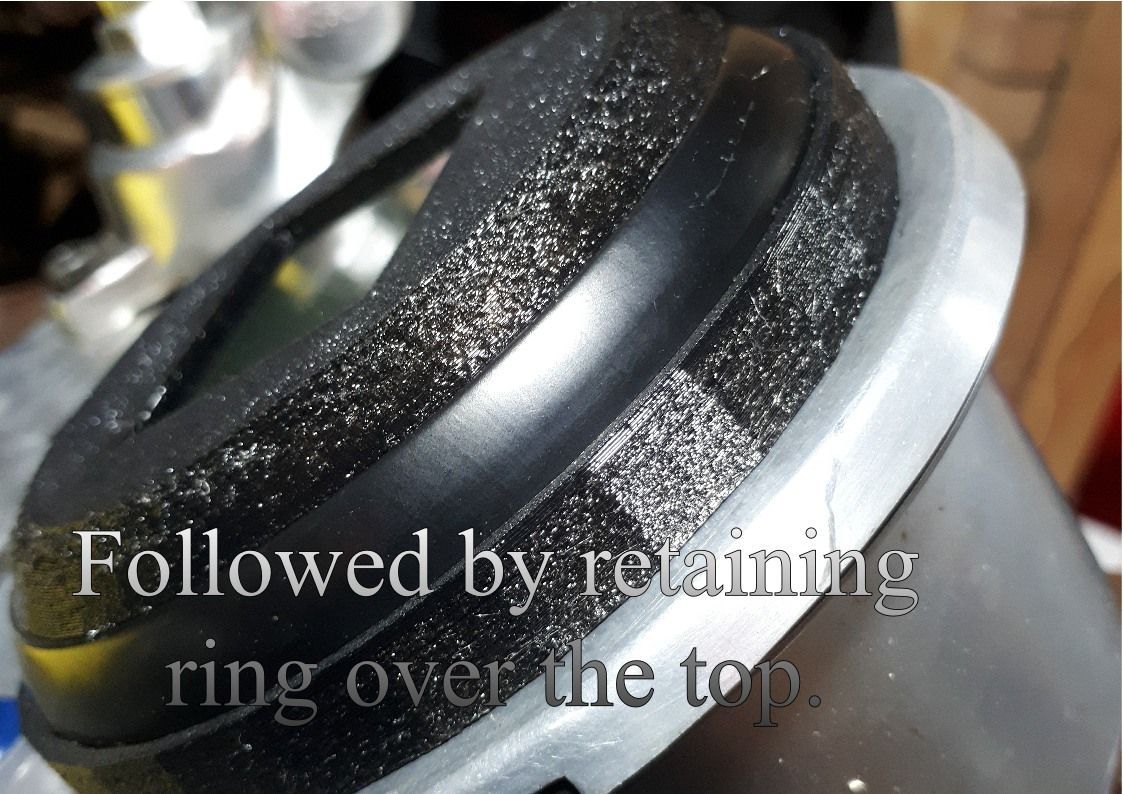
The other problem is that getting a nice print using TPU seems difficult. This means that the finished unit is not much of a looker.
