Offbeat Bikes Magazine
Introduction to motorcycle wiring diagrams

 Wiring and electrics. They seem to strike fear into the heart of even the most seasoned home mechanic. I think we’re all probably more confident with the mechanical aspect of bikes. Usually you can physically see what is broken, what is worn, what isn’t moving when it should and what is moving when it shouldn’t! You can’t actually see all those little electrons that should be careering around the wiring loom; making spark plugs spark, light bulbs light and starter motors turn.

   So, I’m going to attempt a series of articles about the electrical systems on your bike. A few caveats before I start: 1) Electrical systems vary greatly from bike to bike (and even between different model versions of the same bike) and so this will only be a generalised overview. 2) I only work on bikes from the late 80s to 90s, so if you have a Lucas magneto (old bike stuff) or fuel injection (modern bike stuff) I will just look blankly at you. 3) Most of my knowledge of electronics/ electricity was learnt at college 20+ years ago and promptly forgotten after the exam! If I make errors, please forgive me and I hope that some readers with greater, more up to date knowledge may contribute to future articles.

  Having now confessed to my somewhat sketchy knowledge of the subject, you may wonder how any article written by me is going to be of any use to you. Well, what I hope to be able to do is to stop the blind panic that you may experience when first looking at a wiring diagram and get you to use the same powers of reason, logic and deduction that you have and use when confronted with a mechanical problem.

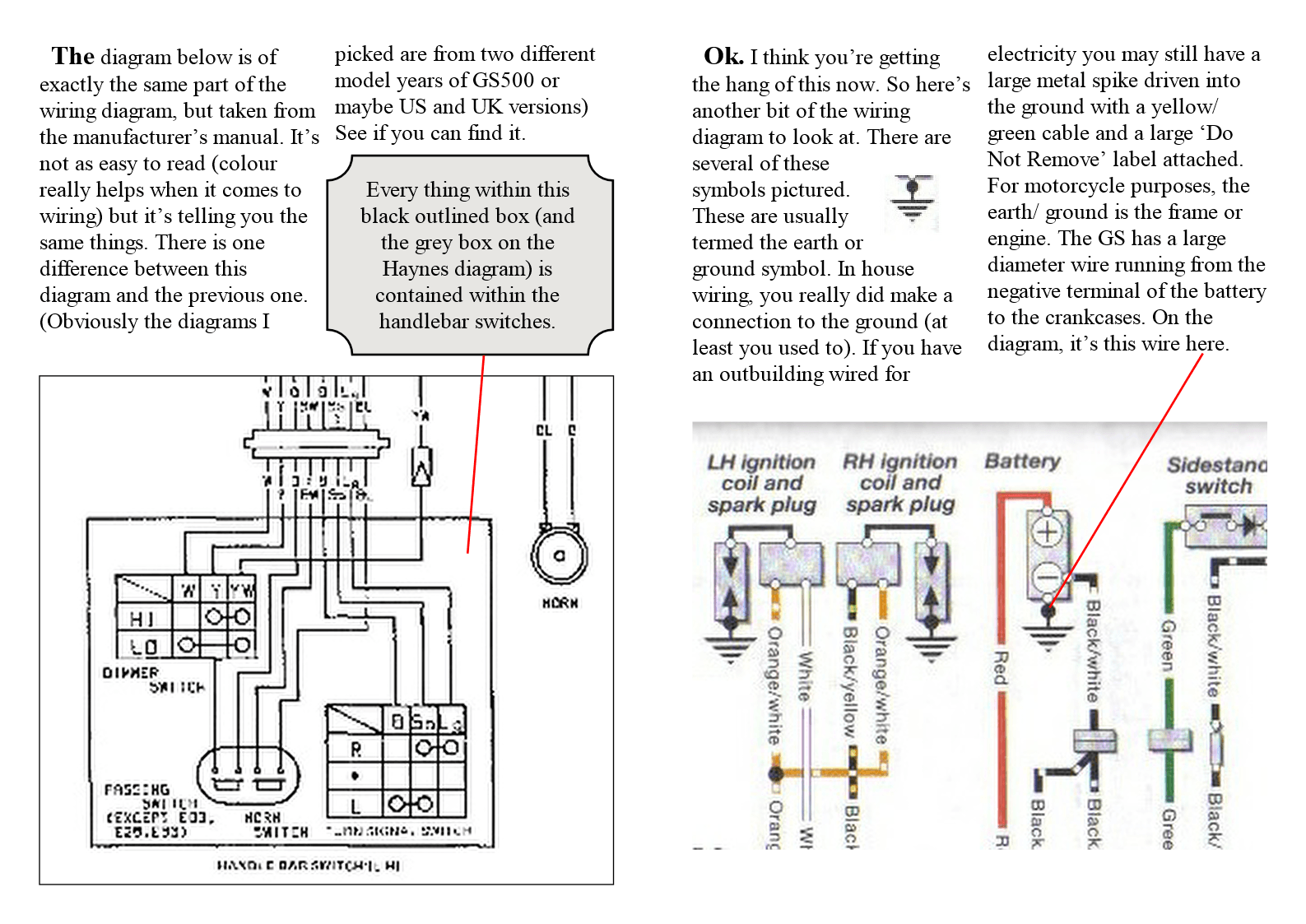
  In this issue, we’re going to look at wiring diagrams (so if you want to have a little panic, scroll down now to see a typical wiring diagram). Now take a deep breath and relax. We’re going to break the diagram down into smaller bits and then it won’t be so scary. The following pages show two wiring diagrams for a GS500. The first one is from Suzuki’s own service manual, the second a Haynes manual version. I suspect all of us find the coloured version a little more user friendly, but essentially they both give us the same information. A Haynes manual is good for hints and tips to help you maintain your bike without special, factory tools, but you get far more detailed information from the factory manual. Factory manuals used to be very expensive (hence the popularity of the Haynes version) but thanks to the internet you can now usually find a cheap (or free) pdf copy.

  In future issues we will be looking at different parts of the electrical system using diagrams and descriptions from the factory manual - information that the Haynes version simply doesn’t contain.
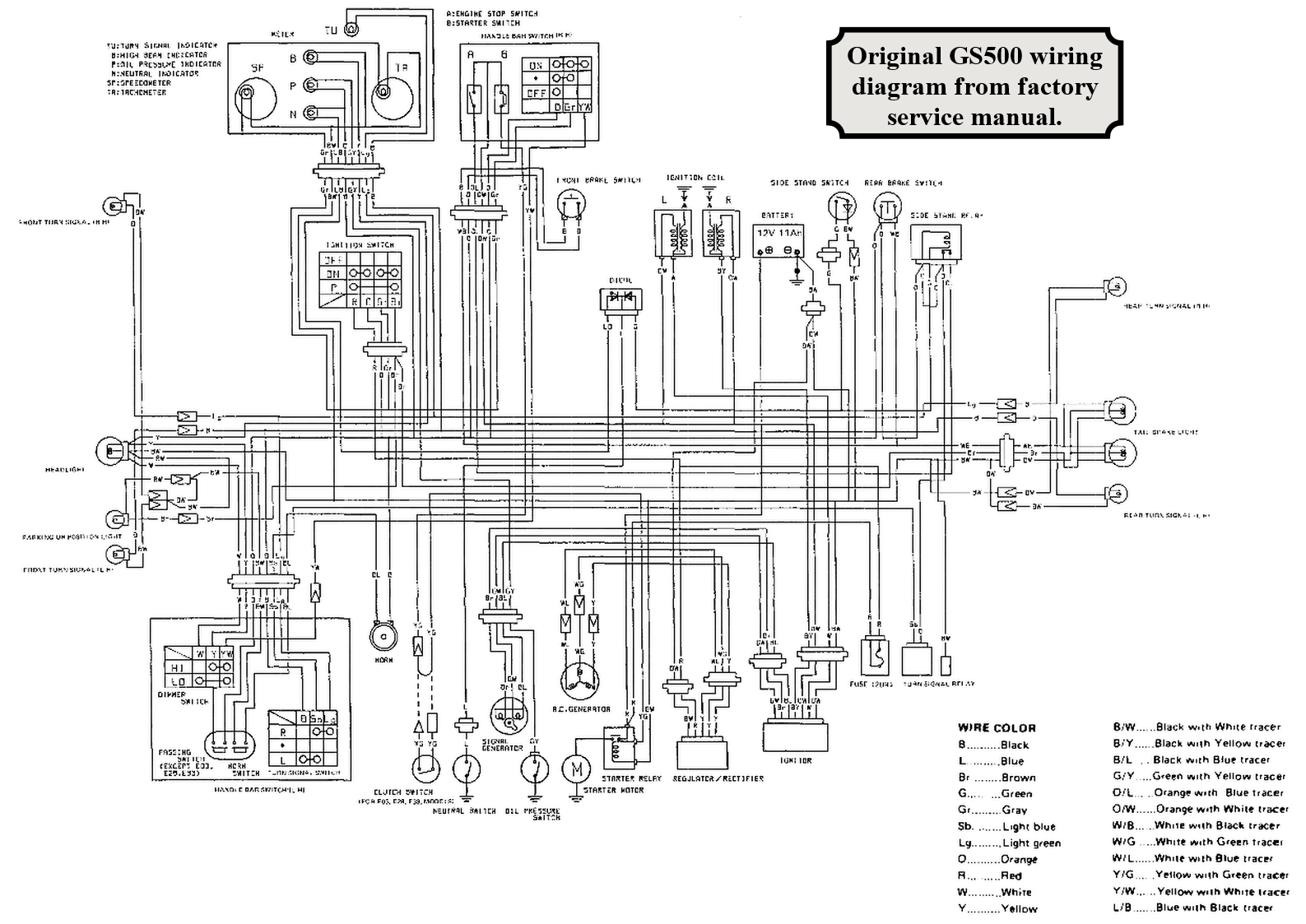
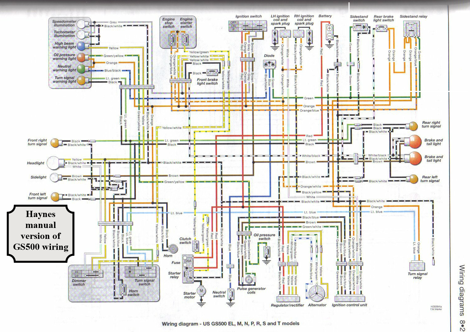
OE GS500 wiring diagram
Haynes GS500 wiring diagram
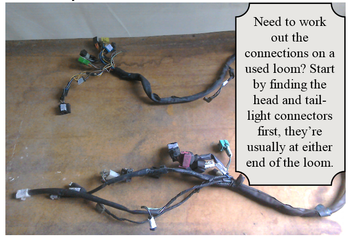
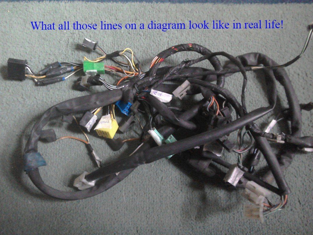
A real GS500 wiring loom
  Back to looking at these wiring diagrams and we’re going to start right at the basics, so that (hopefully) everyone can follow along.
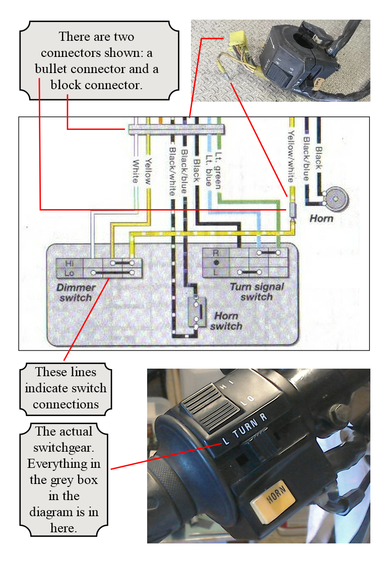
   We’ll start by looking at the left hand switch gear. Wiring diagrams are usually set out with the headlight to the left side of the page, rear light to the right. The left hand switchgear wiring can be found on the left side, bottom area of the page. An enlarged version of this part of the diagram is shown opposite.
  Take a look at the dimmer switch in the diagram. When the switch is in the Lo position, the White wire is connected to the Yellow/ White wire. This is denoted by the horizontal black line. This connection is only made when the switch is in the Lo position. Correspondingly, in the Hi position, the Yellow and Yellow/ White wires are connected. Pressing the horn button connects the Black/ White to the Black/ Blue wire. Now you should be able to see that when the turn signal is in the L position, the Black and Light Blue wires are connected, and when in the R position, the Light Blue and Light Green wires are connected. In the centre (off) position, no connections are made.
  There are also two connectors shown in the diagram. One is a block connector with multiple pins, the other a single bullet connector in the Yellow/ White wire.
  The horn also has connectors (it’s not permanently connected to the wiring loom) but these are less obvious as they are just shown by the little white blobs on the end of the Black and Black/ White wires.
  So now when you look at the wiring diagrams, hopefully you’ll be able to see where to expect connectors, whether they’ll be single or multiple pin plugs and which wires get connected when a switch is operated.
Connectors and switches on motorcycle wiring diagrams
Reading motorcycle wiring diagrams
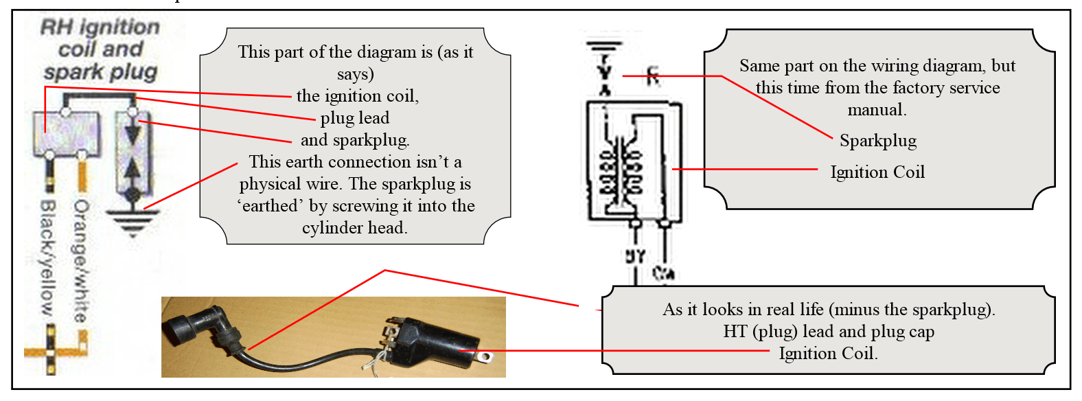
  The diagram makes this wire look small and unimportant. In fact the wire is a good 2ft long and without it your bike won’t go. In every other case where this symbol is shown (for this model and wiring diagram) there is no physical wire. The component in question is ‘earthed’ locally. The spark plug is earthed because it is screwed into the cylinder head, the starter motor is earthed via its metal casing, the neutral and oil pressure switches are also earthed via their mountings. But all of these rely on that main earth wire from the battery to the crankcase to complete the circuit. This is a negative earth circuit (the minus side of the battery is connected to the frame/engine). Beware, you may come across the occasional bike which has a positive earth (plus side of battery connected to frame/engine.
Earthing components in motorcycle wiring
  One final thing to understand on wiring diagrams is the difference between wires crossing on a diagram and wires that are actually joined together. On the coloured (Haynes) version, wires which are joined together are fairly obvious as they have a nice black dot. There is no connector that can come apart, they are physically joined. Joins are less obvious on the other diagram. In this case, the joins are marked as T junctions.
wiring diagrams - joining or crossing
GS500 starter system diagram
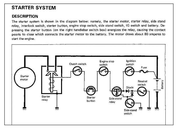
  I think it’s clear to all of us that the coloured Haynes wiring diagram is easier to understand. But now I’m going to show you where the factory manual comes into its own. I want you to look at the starter circuit. By that I mean try and work out which switches have to be in what position in order for the starter motor to turn when I press the start button. You can start following wires around the diagram or you can turn to page 5-18 of the factory manual and find the diagram shown on the left (above on a mobile device).
  This makes life easier. I can see from this diagram that the clutch switch, engine stop switch, ignition switch, starter button, side stand switch and/or neutral switch (not to mention the fuse) will all influence whether the starter motor will turn. There are then five more pages detailing how to test the various parts of this circuit and the line drawings tend to be a lot easier to understand than the black and white photographs of the Haynes manual.
  This all sounds like a sales pitch for buying the factory service manual, but it’s not meant to be. What I’m really trying to say is use as many information sources as possible. It will usually make your life easier.
   If you’ve bought a basket case project bike, the chances are that the loom will be languishing in the bottom of a box. If you’re lucky, the previous owner will have labelled the connectors. If not you’re going to have to work out what they are. Given knowledge of the wiring diagram, you should be able to sort it out.
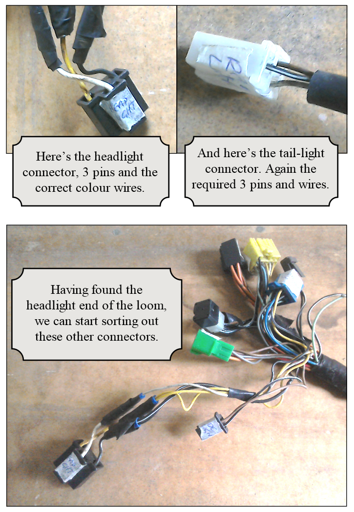
   Since the headlight wiring is usually at one end of the loom and the tail-light at the other, this is always where I start. For the GS, I know that the headlight has three wires; yellow, white and black/white. The tail-light also has three wires; white/black, black/white and brown. So it’s a case of looking for 3 pin connectors with the appropriate colour wires.
Sorting out a wiring loom
wiring heads and tails
  Now you’ve worked out which end the headlight is, you can start looking at the other connectors. We know that at this end of the bike we would be looking for connectors for the ignition switch, handlebar switches, instrument cluster, indicators etc. Again it’s a case of comparing number of pins and wire colours using the wiring diagram as a reference. Gradually you should be able to work your way down the loom and sort out where all the wires go. 
  That’s quite enough about wiring and electrics for this issue. In the next issue, we’re going to be looking at multimeters and how you can use them to fault find your circuits.
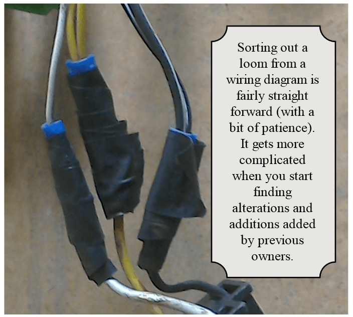
wiring loom additions
Share by: